Troubleshooting the limit circuit
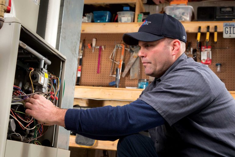
If the furnace you are working on isn’t working, and the board is flashing an open limit circuit code – it’s time to break out the electrical test meter and perform a limit circuit test.
First, start by identifying the limits, located inside the furnace cabinet.
- Main Air Limit: Mounted directly to the firewall inside the cabinet (auto reset)
- Flame Rollout Limit: Attached to the burner section of the furnace (manual reset)
- Inducer Limit: Mounted directly on the inducer motor housing (manual reset)
- Blower Housing Limits: Located on the left and right hand side of the blower housing (auto reset)
Keep in mind: Limits are wired in a series and run on 24 volts (provided by the circuit board inside of the furnace). They are easily identifiable due to the two attached blue wires on either side of the limit.
At EdgeTek, we recommend two different ways of troubleshooting limit circuit – one involves testing the ohms and the other involves checking the voltage.
The process for using ohms is as follow:
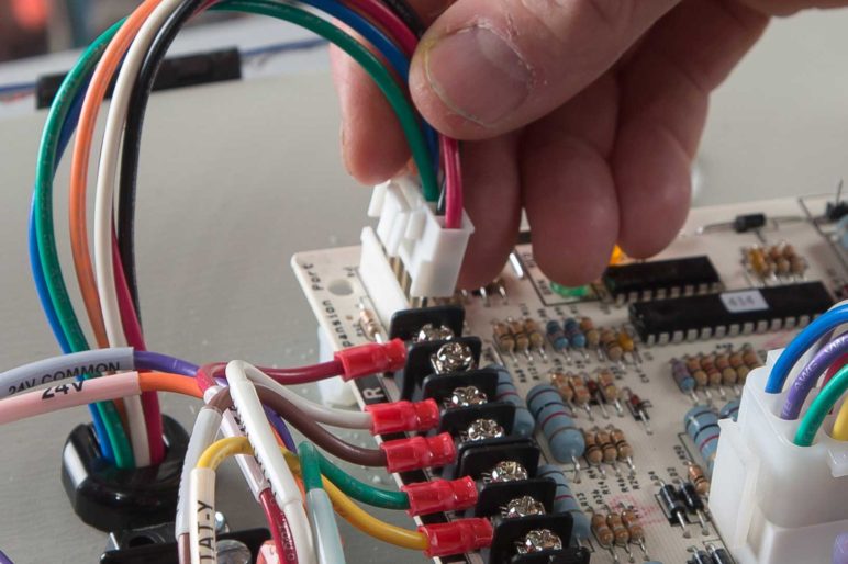
- Disconnect the nine pin Molex plug connector from the furnace (note:a two-stage G7 furnace uses a 12 pin Molex plug connector).
- Hook-up the electrical test meter and set it to ohms.
- Identify the two blue wires on the nine pin Molex connector and test from point to point.
- If it reads 0 ohms, the circuit is closed.
- If it reads 0.1, the circuit is open. (0.1 is the equivalent of infinity).
The process for testing voltage through the circuit itself is as follow:
- Hook-up the electrical test meter and set it to AC voltage.
- Go from point to point, blue wire to blue wire, inside of the Molex connector on the circuit control board.
- If there is not a voltage presence on the electrical test meter, you have a completed circuit.
- If you see 24 AC volts on the electrical test meter, you have an open circuit.
Both of these methods will help you identify the open connections between limits – getting the system back up and running, and making the customer happy.
***NOTE: ONLY USE IF YOU ARE AN HVAC CONTRACTOR. If you are a homeowner trying to dip your toes into the DIY pool – STOP. Serious complications can arise when HVAC installations, repairs or maintenance are performed by someone who is unfamiliar with heating and air conditioning equipment. Drop the wrench, pick up the phone and call a professional.

